




In-Situ Monitoring vs. Post-Process Inspection: Which Method Better Ensures Quality in Additive Manufacturing?
When metal parts are produced using additive manufacturing for demanding industries such as aerospace, medical, and automotive, failure is not an option, and simply having the printer complete a job is not enough. Manufacturers need to be sure there are no hidden pores, poorly fused layers, or deviations invisible to the naked eye. That is why the industry relies on two quality control strategies: in-situ monitoring and post-process inspection. To understand how they differ, we first need to look at the relationship between them.
In-situ monitoring tracks the printing process in real time, layer by layer, acting as an early-warning system. Post-process inspection is not an alternative to it, but rather the step that formally certifies that the finished part meets the required specifications, something monitoring alone cannot guarantee. Both aim to ensure defect-free parts and are particularly important in metal additive manufacturing, where the cost of an undetected defect is higher than in plastic 3D printing.
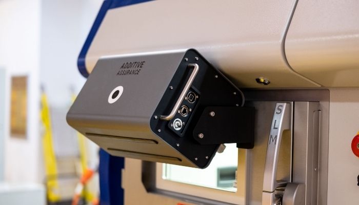
AMiRIS®, Additive Assurance’s in-situ monitoring solution for L-PBF machines (Photo credit: Additive Assurance).
What Is In-Situ Monitoring?
It involves monitoring the printing process as it happens, layer by layer, rather than waiting until the part is finished. The goal is to detect a problem the moment it occurs, so it can be corrected or the print can be stopped immediately before wasting material and time.
How It Works: Key Techniques
During printing, sensors installed inside the machine itself (cameras, photodiodes, pyrometers) capture process data in real time, typically layer by layer. Software analyzes this data and compares it against the expected process parameters: temperature, melt pool shape, and the density of the deposited powder.
If it detects a deviation outside the specified range, the system can trigger an alert, flag the affected area for later review, or even stop the print job before further material and time are wasted on a defective part.
These are the most commercially established techniques:
- Melt pool monitoring: photodiodes or pyrometers mounted coaxially with the laser that measure the temperature and size of the melt pool in real time. This is the most widely adopted technique on the market.
- Layer imaging: cameras that photograph each powder layer before and after laser exposure, detecting defects such as uneven powder distribution or incorrect geometry.
- Optical tomography: a camera-based technique that records the spatial distribution of light emitted during the process to identify defects such as lack of fusion or porosity. This is the basis of systems such as EOSTATE Exposure OT from EOS.
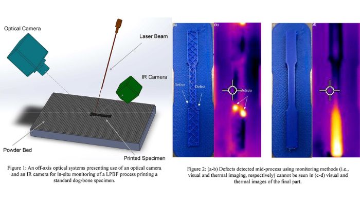
Photo Credit: Youssef AbouelNour y Nikhil Gupta / Materials & Design.
Beyond these techniques, other methods are still in the research or development stage, such as acoustic emission, laser ultrasonics, and real-time X-ray imaging. They could gain ground in the future, but today they remain largely confined to laboratory settings.
What It Detects and Its Limitations
Monitoring is effective at detecting problems related to the printing process itself: porosity, spatter, thermal variations, or melt pool instabilities that could even cause mechanical damage to the printer. Its main limitation is the sheer volume of data it generates and the difficulty of turning that much information into a simple decision.
What Is Post-Process Inspection?
Post-process inspection examines the part after it leaves the printer. Rather than monitoring the process, it evaluates the final result. For example, it checks whether the geometry matches the original design and whether there are internal defects that cannot be seen with the naked eye.
How It Works: Key Techniques
Once the part leaves the printer, or after additional steps such as heat treatment or support removal, it is sent to a dedicated inspection station, separate from the machine that built it. There, two types of checks are combined: an external check, which compares the part’s geometry against the original design, and an internal check, which looks for hidden defects such as pores or lack of fusion. Only if the part passes both checks is it considered fit for use.
These are the most widely used techniques in the industry:
- Computed tomography (CT): uses X-rays to generate a complete 3D model of the part, allowing its internal structure to be compared against the original CAD file. It is the gold standard for critical parts.
- Coordinate measuring machine (CMM): measures the part’s external geometry with high precision.
- Structured-light 3D scanning: captures the part’s surface without contact for comparison with the original design.
- Digital radiography: produces a two-dimensional image of material density and thickness, offering a faster and more cost-effective alternative to full CT.
- Ultrasonic testing: uses high-frequency sound waves to detect internal defects such as cracks or lack of fusion.
- Dye penetrant testing: applies a colored or fluorescent liquid that reveals surface cracks invisible to the naked eye.
- Mechanical testing and metallography: uses destructive tests (tensile, fatigue, hardness, microstructural analysis) to validate the material’s actual properties.
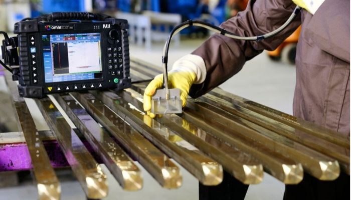
Ultrasonic testing on metal profiles (Photo credit: Applus+ BKW).
Alongside these, more specialized or recently adopted techniques are used mainly in specific applications, such as aerospace part qualification.
What It Detects and Its Limitations
Post-process inspection is the only way to formally certify that a finished part meets the required specifications, which is essential in industries such as aerospace and medical. However, it comes at a significant cost: it can only be performed once the part is complete, so by the time a defect is found, the material and machine time have already been wasted. In addition, computed tomography is expensive and loses sensitivity on large parts.
Now that we’ve looked at how each approach works, the table below summarizes their main differences:
| Criterion | In-Situ Monitoring | Post-Process Inspection |
|---|---|---|
| Detection timing | During printing, layer by layer | After the part is complete |
| What it mainly detects | Process deviations: temperature, melt pool instability, powder recoating defects | Defects in the finished part: geometric deviations, internal porosity, lack of fusion |
| Cost when a defect is found | Low: the print can be stopped in time | High: material and machine time already spent |
| Access to the part | Only the surface exposed in each layer | Complete, including the interior (with CT) |
| Role in certification | Complementary; does not replace formal certification | The established reference, addressed by standards such as ASTM E3166 |
| Typical industries | Metal additive manufacturing in general, especially series production | Aerospace, medical, automotive |
| Maturity | Medium to high (key techniques already factory-integrated) | High (techniques established for decades) |
Monitoring and Inspection Solutions
The in-situ monitoring market is dominated by both printer manufacturers themselves and specialized providers whose systems integrate with machines from different brands. EOS, for example, offers its own solution, EOS Smart Monitoring, which is built directly into its industrial metal printers and combines optical tomography with closed-loop control. Among independent providers, Phase3D (formerly known as Additive Monitoring Systems) stands out. Its Fringe Inspection system uses structured light to measure the powder bed layer by layer with high dimensional accuracy. In 2026, the company announced its integration with the EOS M4 ONYX printer, following its work with NASA and the U.S. Air Force.
Renishaw, another well-known name in this field, announced a collaboration with Addiguru and Apex that same year to further advance in-situ monitoring. In the melt pool monitoring space, Sigma Labs has established its PrintRite3D system as a preferred option within DMG MORI’s LASERTEC line. Australia-based Additive Assurance follows a similar approach with its AMiRIS system, which has been integrated into printers from both Additive Industries and Nikon SLM Solutions, two key manufacturers in the industry.
In terms of the required investment, the two strategies start from very different points. The most basic in-situ monitoring systems, such as a camera with image processing, can cost between $7,000 and $12,000 (approximately €6,100 to €10,500), according to a component-level cost breakdown published by specialists in the metal additive manufacturing sector. Factory-integrated solutions for industrial printers, such as those from EOS or Sigma Labs, are priced on a case-by-case basis, with no published reference price.
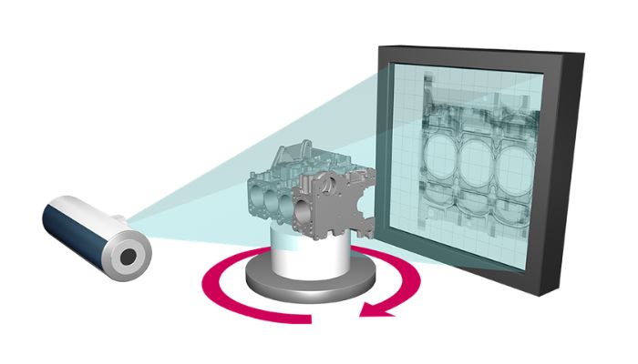
Computed tomography uses X-rays to generate a complete 3D model of a part (Photo credit: Comet Yxlon).
Post-process inspection, on the other hand, requires a much larger investment. According to Zeiss, a manufacturer of metrology and industrial computed tomography equipment, a CT scanner can cost anywhere from $100,000 to more than $1 million (approximately €88,000 to over €880,000), depending on its resolution and capacity. In addition, while in-situ monitoring is typically integrated directly into the printer’s own software, Zeiss notes that its CT systems include dedicated training modules, suggesting a steeper learning curve.
So, Which One Wins?
After all this, the honest answer is that there is no winner. In-situ monitoring and post-process inspection do not compete with each other; they complement one another. The former acts as an early-warning system during printing, preventing further material and machine time from being invested in a part that is no longer viable. The latter is, for now, the only way to formally certify that a finished part meets the required specifications. In fact, it is the method addressed by standards such as ASTM E3166 for additively manufactured metal aerospace parts.
The industry trend also points directly toward combining both approaches within the same workflow. It is increasingly common for metal additive manufacturing companies to use in-situ monitoring as a first filter and reserve post-process inspection only for parts that pass that initial check, rather than treating them as two separate stages.
Both strategies address the same question: how do we know that a 3D-printed part is safe to use? In-situ monitoring keeps watch over the process as it happens. Post-process inspection certifies the final result. And as metal additive manufacturing gains ground in demanding industries, we will likely see fewer companies choosing between the two and more adopting both as part of the same quality control workflow.
What do you think of these two approaches to ensuring part quality? Let us know in a comment below or on our LinkedIn or Facebook pages! Plus, don’t forget to sign up for our free weekly Newsletter to get the latest 3D printing news straight to your inbox. You can also find all our videos on our YouTube channel.
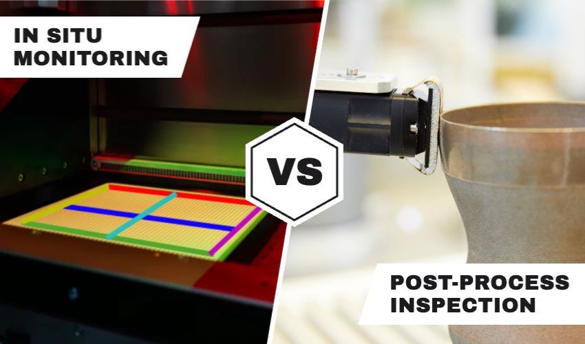
*Cover photo: On the left, a line scan performed with Phase3D’s Fringe Inspection solution (credit: Phase3D). On the right, nondestructive testing of additively manufactured parts (credit: CEA).







I was reading about in-situ monitoring for metal AM and it got me thinking about how different industries handle real-time feedback versus after-the-fact checks. Reminds me of when I tried learning Noomiclone at noomiclone.cc and kept resetting mid-flip because I could tell immediately when my arch was off—way better than finding out after the landing.